Introduction
In the ongoing assessment of chloride equilibrium concentrations in bentonite, we here take a closer look at the study by Ishidera et al. (2008), in the following referred to as Is08. We thus assess the 7 points indicated here

The study consists of chloride and iodide though-diffusion tests in sets of samples of “Kunigel V1” bentonite, mixed with either 0%, 30%, or 50% silica sand. Here we mainly focus on the chloride tests. Also, we exclude the samples with 50% sand, as the montmorillonite content is judged to small. For each type of material, chloride diffusion tests were performed with NaNO3 background concentrations 0.01 M, 0.5 M, and 5.0 M. All samples are cylindrical with diameter 2 cm and height 1 cm (giving a volume of 3.14 cm3) and have dry density 1.6 g/cm3, which means that the effective montmorillonite density varies in the different test sets. To refer to a single test we use the notation “sand mixture percentage/background concentration”, e.g. “30/0.5” refers to the test made on the sample with 30% sand and with background concentration 0.5 M.
A single additional test was performed on purified “Kunipia F” material, at dry density 0.9 g/cm3 and a background concentration of 5.0 M NaNO3. This density was chosen in order to have a similar effective montmorillonite dry density as the “Kunigel V1” samples with 30% sand.
All tests were performed at elevated pH in the external solution of 12.5 (initially), and the Cl diffusion tests were performed in a N2 glove box, with vanishing CO2 and O2 pressures. In total we here investigate 7 tests (of the 22 tests in the full study, we exclude 12 that concern iodide diffusion, and 3 that have 50% sand). In addition to the published article, these tests are also reported in a technical report (in Japanese).
Materials
“Kunigel V1” and “Kunipia-F” are simply brand names rather than materials specifically aimed for scientific studies. This is similar to e.g. “MX-80” and “KWK”, that we have encountered in previous assessments.
I have found it rather difficult to obtain official data on “Kunigel V1” and “Kunipia F”; data sheets or technical specifications do not seem readily available online. Moreover, the Japan Atomic Energy Agency seem to contain their data within a database, and restrict its usage (this site seems a bit deserted, though). Fortunately, the open scientific literature contains some entries. These sources, however, provide quite different values for e.g. montmorillonite content and exchangeable cations in “Kunigel V1”.
Montmorillonite content
Several studies of “Kunigel V1” — including Is08 — refer to a single source for e.g. mineral content and cation exchange capacity: Ito et al. (1994),1 which states that “Kunigel V1” contains 46% — 49% montmorillonite. Other sources, however, claim considerably different numbers; e.g. Cai et al. (2024) states a montmorillonite content of 54.3%, while Kikuchi and Tanai (2005) states 59.3%.
Here, I do not intend to critically assess these various sources, but simply conclude that the montmorillonite content stated in Is08 must be viewed with some skepticism. The study they reference (Ito et al. (1993)) is significantly older than their own, and they do not indicate that they have investigated the material actually used. In this assessment we adopt an uncertainty for the montmorillonite content in “Kunigel V1” of 45% — 60%.
Concerning “Kunipia F” most sources I have investigated state a montmorillonite content above 99%, although some — including Is08 — set a lower limit at 95%. Here we assume that the montmorillonite content of “Kunipia F” lies in the interval 95% — 100%.
Cation population
Reports on cation exchange capacity (CEC) and exchangeable cations in “Kunigel V1” are also quite scattered in the scientific literature, as demonstrated in the table below.
| Source | CEC (eq./mol) | Na (eq./mol) | Ca (eq./mol) | Mg (eq./mol) | K (eq./mol) |
| Dohrman et al. (2025) | 0.61 | 0.57 | 0.04 | 0.01 | \(<\) 0.01 |
| Cai et al. (2024) | 0.784 | 0.619 | 0.164 | 0.013 | \(<\) 0.01 |
| 0.622 | (0.448) | (0.018) | \(<\) 0.01 | ||
| Dohrman et al. (2013) | 0.62 | 0.60 | 0.04 | \(<\) 0.01 | 0 |
| 0.64 | 0.59 | 0.04 | \(<\) 0.01 | 0 | |
| 0.59 | 0.60 | (0.21) | (0.02) | \(<\) 0.01 | |
| 0.60 | 0.60 | (0.17) | (0.01) | \(<\) 0.01 | |
| Svensson et al. (2011) | 0.671 | ||||
| 0.632 | |||||
| 0.638 | |||||
| 0.756 | |||||
| Komine (2008) | 0.732 | 0.405 | 0.287 | 0.030 | 0.009 |
| Kikuchi and Tanai (2005) | 0.75 | 0.638 | (0.480) | (0.05) | 0.03 |
| Ochs et al. (1998) | 0.601 | 85.3% | 10.9% | 2.3% | 1.5% |
| Sasaki et al. (1994) | 0.601 | 0.513 | (0.471) | (0.088) | 0.001 |
| Ito et al. (1994) | 0.556 | ||||
| 0.564 |
CEC values (roughly) in the range 0.55 — 0.80 eq/kg are reported. These numbers will not be further assessed here, and we will assume an uncertainty of this range for the CEC in “Kunigel V1”.
One observation to be made is that some of the sources reporting relatively high CEC also reports relatively high montmorillonite content. The data from e.g. Kikuchi and Tanai (2005) gives an estimate of the cation exchange capacity for the montmorillonite of 0.75/0.593 eq./kg = 1.26 eq./kg, while the data from Ito et al. (1994) gives roughly 0.556/0.475 eq./kg = 1.17 eq./kg. These numbers are quite consistent and suggest that the reported differences in CEC may partly be due to differences in montmorillonite content in different batches of “Kunigel V1”.
We can further conclude that the reported amount of exchangeable sodium in “Kunigel V1” is rather stable (with some exception), while the amount of exchangeable calcium and magnesium scatter significantly. This scatter is mainly due to interference of soluble accessory minerals (see below; entries in the above table where such interference is obvious are put within parentheses). Thus, the exchangeable cation population in “Kunigel V1” can be estimated to about 80% — 90% sodium and about 10% — 20% di-valent ions (calcium and magnesium).
Some cation data for “Kunipia F” found in the literature is listed in the table below (the table contains a few entries for the variants “Kunipia-G” and “Kunipia-P”; these are indicated).
| Source | CEC (eq./mol) | Na | Ca | Mg | K |
| a b c d e f g | 1.19 | ||||
| h | 1.2 | ||||
| i | 1.0 | ||||
| j | 1.13 | ||||
| k | 1.13 (1.15) | ||||
| l | 1.22 | ||||
| m | 1.15 | ||||
| n | 1.114 | ||||
| o | 1.165 | ||||
| p | 1.08 | 97.1% | 0.7% | 1.3% | 0.9% |
| q | 1.165 | 1.14 | 0.206 | 0.029 | 0.011 |
| r (Kunipia P) | 1.07 | ||||
| s (Kunipia F & P) | 1.0 — 1.1 | ||||
| t (Kunipia G) | 1.088 | 83% | 12% | 5% | 0% |
| u (Kunipia G) | 1.15 | 91% | 8% | 0% | 1% |
The most commonly reported CEC value in this little survey is 1.19 eq./kg, and I suspect that this has been supplied by the manufacturer (although the value 1.15 eq./kg has also been reported as a given from the manufacturer). As “Kunipia F” is mainly pure montmorillonite, note that this value (1.19) is consistent with the montmorillonite CEC estimated from “Kunigel V1” above. That being said, the scatter in reported CEC for “Kunipia F” is in the range 1.0 — 1.22 eq./kg.
The few reported cation populations of “Kunipia F” (and the variant “Kunipia G”, which is supposed to be identical in composition) that I have found have a higher sodium content as compared with “Kunigel V1”, roughly in the range 85% — 95%.
Soluble accessory minerals
Basically all sources I have encountered — including Is08 — say that “Kunigel V1” contains smaller amounts of calcite and dolomite. This is also quite evident from some of the reported results on exchangeable cations, where the sum of these substantially exceeds the evaluated CEC. Obviously, the presence of additional calcium and magnesium contribute to the uncertainty and complexity when evaluating effects of ion equilibrium in this material (just as for the cases of “MX-80” and “KWK”).
Sample density
The samples in Is08 were ultimately sectioned and analyzed (for the final state concentration gradient). Is08 nowhere state that they measured density of these sections. We thus proceed with using the nominal density of 1.6 g/cm3. Using the above estimated uncertainty in montmorillonite content we get the following intervals for the effective montmorillonite density
| Samples | EMMD interval (g/cm3) |
| 0% sand | 1.05 — 1.24 |
| 30% sand | 0.83 — 1.01 |
| Kunipia F | 0.87 — 0.90 |
Note that these intervals do not include uncertainty due to variation in density of the actual samples.
Uncertainty of external solutions
The samples were prepared by first saturating them with deionized water for more than two weeks, and thereafter contacting them with NaNO3 solutions for more than five weeks.
We have no reason to doubt the accuracy of the initial concentration of the salt solutions, but contacting a bentonite containing di-valent ions with pure sodium solutions inevitably initiates an ion exchange process. We have made the same conclusion for studies using “MX-80” and “KWK” bentonite. Similar to the previous studies, Is08 do not keep track of the exact chemical evolution of the external solutions, but we can calculate an estimate of the extent of the sodium-for-di-valent exchange.

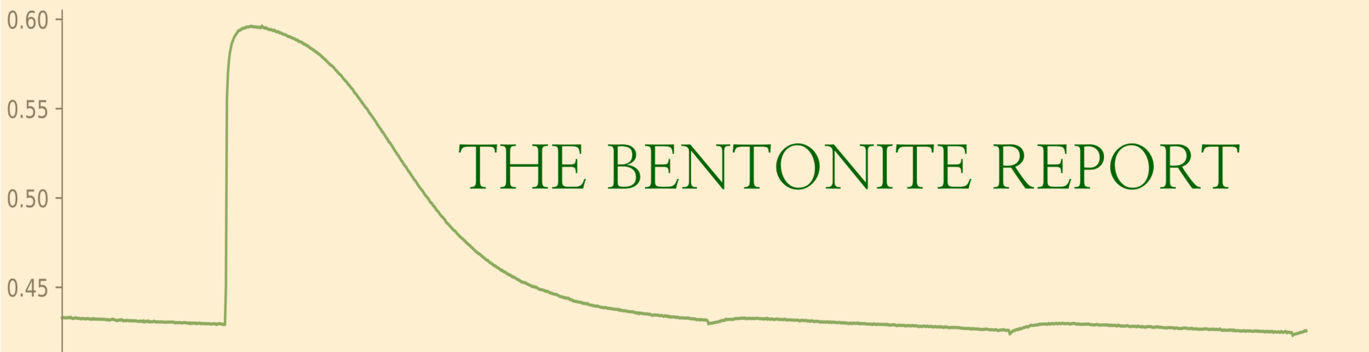
The above diagram shows the result of equilibrating the specified amount of bentonite (3.14 cm3) with the specified amount of external solution (100 ml) for different initial NaNO3 concentrations. The calculation assumes that the bentonite only contains sodium and calcium, with an initial calcium content of 15%, a selectivity coefficient of 5 M, and a cation exchange capacity of of 0.65 eq/kg. The diagram shows the amount of calcium left in the sample after equilibration, as a function of initial NaNO3 concentration for the cases of 0% and 30% mixed-in silica sand. The dashed vertical lines indicate the external concentrations in the performed tests. We note — as we have done for several other studies — that the equilibrium amount of di-valent ions still in the bentonite depends significantly on the initial NaNO3 concentration: tests performed at 0.5 M and 5.0 M gives essentially a pure sodium clay, while samples used at 0.01 M still contain the initial 15% di-valent ions in the clay.
Since the “Kunipia F” material only is used in a test with background concentration of 5.0 M, we can quite safely assume that the exchangeable cation population in this particular test is basically 100% sodium.
It should be noted that the calculations have not accounted for the additional di-valent ions present in the bentonite in form of accessory minerals (calcite, dolomite). They thus probably underestimate the amount di-valent ions still left in the clay after equilibration.
Evaluations from the diffusion tests
The diffusion tests were performed by sandwiching the clay samples between a source and target reservoir of equal volumes, 50 ml. The initial Cl tracer concentration was 0.05 mM in the source reservoir, and 0.0 mM in the target reservoir.
The tracer concentration in both the source and target reservoirs were periodically measured, but as far as I understand, none of the reservoir solutions were replaced during a test. This means that a certain concentration build-up occurs in the target reservoir, and a corresponding concentration drop occurs in the source reservoir.
The test set-up furthermore involves quite wide “filter” components at the interfaces between clay and reservoirs.2 Is08 mean that these components restrict diffusion to such an extent that they must be included in the test analyses. With a rather complex set-up that involves evolving reservoir concentrations and “filter” influence, the preferred way to evaluate them would be a full simulation of the whole process. This is however not the procedure followed in Is08 (below we make such simulations).
Instead, Is08 center most of their evaluation around the measured steady-state flux,3 taking filter diffusion into account. In the blog post on on filter influence on through-diffusion tests we derived an expression for the steady-state flux, which can be written
\begin{equation} j^\mathrm{ss} = -D_e\frac{1}{1+\omega}\frac{\Delta c_\mathrm{res}}{L} \tag{1}\end{equation}
where \(D_e\) is the effective diffusivity, and \(L\) the length of the clay component. \(\Delta c_\mathrm{res}\) is the difference in concentration between the two reservoirs, and \(\omega\) is the relative filter resistance, given by
\begin{equation} w = \frac{2D_eL_f}{D_fL} \tag{2} \end{equation}
where \(D_f\) and \(L_f\) denote effective diffusivity and length of the two confining “filters” (assumed identical).
Solving eq. 1 for \(D_e\) gives
\begin{equation} D_e = – \frac{j^\mathrm{ss}L}{\Delta c_\mathrm{res} + \frac{2j^\mathrm{ss}L_f}{D_f}} \tag{3}\end{equation}
which is the same expression as found in Is08 (eqs. 2 and 3 in Is08).
\(D_e\) is thus evaluated in Is08 by measuring \(j^\mathrm{ss}\) and \(D_f\), estimating \(\Delta c_\mathrm{res}\), and knowing the lengths of the clay and filter components (\(L\) = 1 cm, \(L_f\) = 1.5 cm). Note that this is a quite involved procedure, necessitated by the test design: the source reservoir is small enough for the concentration to significantly drop during the course of a test; the target is not replaced during the course of a test, resulting in an increasing concentration significantly different from zero; the sample is sandwiched between wide “filter” components; and, as far as I can tell, the external solutions are not stirred or circulated. With a simpler test design, the reservoir concentration difference could have been kept effectively constant, and influence from confining filters could have been avoided (the only case, really, where filter influence is unavoidable is for cation through-diffusion at low ionic strength). With this being said, a re-evaluation of the results demonstrates that the “filter” influence, after all, is quite moderate. We will further discuss this below.
Is08 estimate \(\Delta c_\mathrm{res}\) by using the average source reservoir concentration during the course of a test (\(\bar{c}_\mathrm{source}\)), and by assuming zero target reservoir concentration, i.e. \(\Delta c_\mathrm{res} = 0-\bar{c}_\mathrm{source}\). I do not really understand this, because the target reservoir concentration is clearly not zero; since the two reservoirs have the same volume it seems more reasonable to assume that the concentration drop in the source reservoir corresponds to an equal concentration increase in the target reservoir.4
The “filter” diffusivities are claimed to be measured in separate tests without clay components, but the reported values does not make full sense to me. It is claimed that three different values for \(D_f\) were used for the three different background concentrations. But we do not expect any significant difference in diffusivity due to background concentration. Does this mean that tests performed at a specific background concetration all used the same test cell, while different test cells were used for different background concentrations? Furthermore, the specified values are \(D_f = 3\cdot 10^{-10}\) m2/s for background concentration 0.01 M, \(D_f = 2.6\cdot 10^{-9}\) m2/s for background concentration 0.5 M, and \(D_f = 1.8\cdot 10^{-9}\) m2/s for background concentration 5.0 M. The \(D_f\) values at high background concentration are thus not only almost an order of magnitude higher than that for 0.01 M background, these values also implies a diffusivity larger than for pure bulk water.5
If we anyway use these values for \(D_f\) to calculate the relative filter resistances (eq. 2) we get maximum values for \(\omega\) of 0.077, 0.037, and 0.055 for background concentrations 0.01 M, 0.5 M, and 5.0 M, respectively (anticipating the evaluated \(D_e\) values in table 1 in Is08). These values are tiny, showing that their own estimations indicate insignificant “filter” influence.
In the following we de-derive the values for \(j^\mathrm{ss}\) and \(\Delta c_\mathrm{b}\) (the final clay concentration difference) used for evaluating the reported values of \(D_e\), “\(D_a\)”, and \(\epsilon_\mathrm{eff}\),6 and compare them with the raw flux and concentration profile data (available for the tests performed with 30% sand mixture).
Steady-state fluxes
The steady-state fluxes are nowhere stated explicitly in Is08, but it is straightforward to read them off from the provided “breakthrough curves”. To check the consistency of the reported parameters we may use these values and the reported values for \(D_f\) and \(D_e\) to back-calculate \(\Delta c_\mathrm{res}\) using eq. 3.
| Test | \(j^\mathrm{ss}\) (Is08, fig. 2) (10-10 mol/m2/s) | \(D_e\) (Is08, tab. 1) (10-11 m2/s) | \(D_f\) (10-10 m2/s) | \(\Delta c_\mathrm{res}\) (eq. 3) (mM) | \(\Delta c_\mathrm{res,ex}\) (mM) |
| 30/0.01 | 0.38 | 0.77 | 3.0 | -0.053 | -0.049 |
| 30/0.5 | 1.66 | 3.20 | 26 | -0.054 | -0.048 |
| 30/5.0 | 2.10 | 3.30 | 18 | -0.067 | -0.048 |
In this table are also listed the “expected” values of of the reservoir concentration differences, \(\Delta c_\mathrm{res,ex}\), estimated from subtracting the average concentration increase in the target reservoir from from 0.05 mM. We see that the reported values of \(D_e\) “overestimates” \(\Delta c_\mathrm{res}\) by 8% — 40%.
We do not have more information to assess whether this mismatch is due to some actual inconsistency in the reported values or if it indicates that the concentration difference stated in the article was not actually what was achieved in the experiment. In any case, this is low quality scientific reporting.
Concentration profile gradients
We can, however, continue by also checking the consistency of the estimated pore diffusivity, \(D_p\),7 which was evaluated by measuring the concentration gradient in the clay at the termination of the tests (\(\Delta c_b/L\)).8
\begin{equation} D_p = -\frac{j^\mathrm{ss}L}{\Delta c_b} \tag{4}\end{equation}
The concentration gradients are not explicitly stated in the article, but we can read them off from the published concentration plots. By using the tabulated values of \(D_p\) we can use eq. 4 to back-calculate what values for the steady-state flux was used for their evaluation.
| Test | \(\Delta c_\mathrm{b}\) (Is08, fig. 4) (mM) | \(D_p\)7 (10-10 m2/s) | \(j^\mathrm{ss}\) (eq. 4) (10-10 mol/m2/s) |
| 30/0.01 | -0.00191 | 1.8 | 0.34 |
| 30/0.5 | -0.00687 | 2.4 | 1.65 |
| 30/5.0 | -0.00901 | 1.6 | 1.44 |
Note that some of these values of \(j^\mathrm{ss}\) are smaller than what can be read off from the “breakthrough curves”. In particular, the value for the 30/5.0 test is reduced by more than 30%. If we use these values of \(j^\mathrm{ss}\) to re-calculate the corresponding reservoir concentration differences, we get
| Test | \(j^\mathrm{ss}\) (from \(\Delta c_b\)) (10-10 mol/m2/s) | \(D_e\) (Is08, tab. 1) (10-11 m2/s) | \(D_f\) (10-10 m2/s) | \(\Delta c_\mathrm{res}\) (eq. 3) (mM) | \(\Delta c_\mathrm{res,ex}\) (mM) |
| 30/0.01 | 0.34 | 0.77 | 3.0 | -0.048 | -0.049 |
| 30/0.5 | 1.65 | 3.20 | 26 | -0.053 | -0.048 |
| 30/5.0 | 1.44 | 3.30 | 18 | -0.046 | -0.048 |
Although the calculated value for \(\Delta c_\mathrm{res}\) still is larger than 0.05 mM for the 30/0.5 test, these values are now generally in better agreement with the “expected” estimations.
I do not really know what to make of these results. For the 30/0.01 and 30/0.5 tests, the slightly different results perhaps reflect the uncertainty in the estimation of \(j^\mathrm{ss}\) and \(\Delta c_b\). But there is clearly something wrong with the evaluation of the 30/5.0 test. From the diagram (fig. 2 in Is08), it is, for example, clear that this test has the largest flux.
Chloride equilibrium concentrations
The chloride equilibrium concentration is evaluated in Is08 in terms of an “effective porosity,”6 \(\epsilon_\mathrm{eff} = D_e / D_p\). But from eq. 3 and eq. 4 we see that it is really evaluated from
\begin{equation} \epsilon_\mathrm{eff} = \frac{\Delta c_b}{\Delta c_\mathrm{res} + \frac{2j^\mathrm{ss}L_f}{D_f}} \tag{5} \end{equation}
Note that the factors \(j^\mathrm{ss}L\) cancel; the evaluation of \(\epsilon_\mathrm{eff}\) is therefore less sensitive to the estimation of \(j^\mathrm{ss}\) (the flux only appear in the correction term due to filter influence). Thus, even if the evaluation of \(j^\mathrm{ss}\) evidently has its flaws, the evaluation or \(\epsilon_\mathrm{eff}\) is more robust. This reflects the fact that the equilibrium concentration, as the name suggest, does not depend on transport quantities; as is clear from eq. 5, \(\epsilon_\mathrm{eff}\) is simply an interpretation of the clay concentration (\(c_b\)). We have discussed this issue several times before.
Eq. 5 also shows that the uncertainty in estimating the equilibrium concentration (or \(\epsilon_\mathrm{eff}\)) mainly stem from uncertainties in \(\Delta c_\mathrm{res}\), and uncertainty stemming from filter resistance (\(2j^\mathrm{ss}L_f/D_f\)). Both of these uncertainties could have been avoided with a better test design — if filter resistance was avoided, and if the source and target reservoirs were kept at (virtually) constant concentrations, the equilibrium concentration would be given directly from the clay concentration profile.9
One way to estimate the effects of these uncertainties is to simply compare the reported values for \(\epsilon_\mathrm{eff}\) with the ratio \(\Delta c_b/\Delta c_\mathrm{res,init}\), where \(\Delta c_\mathrm{res,init}\) = -0.05 mM is the initial reservoir concentration difference.
| Test | \(\Delta c_\mathrm{b}/\Delta c_\mathrm{res,init}\) | \(\epsilon_\mathrm{eff}\) |
| 30/0.01 | 0.038 | 0.043 |
| 30/0.5 | 0.14 | 0.13 |
| 30/5.0 | 0.18 | 0.21 |
The differences are not that great, demonstrating that reported values of equilibrium concentrations (\(\epsilon_\mathrm{eff}\)) are quite robust, even though we have found inconsistencies in the underlying transport quantities.
Why not just simulate the whole thing?
A better way, in my view, to extract the equilibrium concentrations from this rather complex test set-up is to simulate the tests completely. This is done here, taking into account the external reservoir, the “filter” components and using the homogeneous mixture model for the bentonite component. Note that the homogeneous mixture and the effective porosity models are equivalent when it comes to modeling this type of diffusion: the effective porosity parameter can be calculated from \(\epsilon_\mathrm{eff} = \phi\cdot\Xi\), where \(\phi\) is the physical porosity and \(\Xi\) is the ion equilibrium coefficient. Similarly, the diffusion coefficient in the homogeneous mixture model (\(D_c\)) can in this case directly be identified with the pore diffusivity in the effective porosity model (\(D_p\)). In these simulations we used \(\Xi\) and \(D_c\) as fitting parameters.
The fitted parameters are listed in the table below and compared to the reported values of \(D_p\) and \(\epsilon_\mathrm{eff}\).
| Test | \(D_c\) (10-10 m2/s) | \(D_p\) (10-10 m2/s) | \(\Xi\) | \(\phi\cdot\Xi\) | \(\epsilon_\mathrm{eff}\) |
| 30/0.01 | 2.14 | 1.8 | 0.103 | 0.043 | 0.043 |
| 30/0.5 | 2.50 | 2.4 | 0.457 | 0.19 | 0.13 |
| 30/5.0 | 2.39 | 1.6 | 0.625 | 0.26 | 0.21 |
Below is the simulated outflux curves and final state clay concentration profiles compared with experimental data.
0.01 M background concentration:

0.5 M background concentration:

5.0 M background concentration:

The simulations were performed both with (green lines) and without (red lines) including filters. It may be noted that both models can be fitted equally well, confirming that filter effects are after all small in these tests. Also, although the diffusion parameters change to some extent, the fitted ion equilibrium coefficients are essentially the same regardless of whether filters are included or not. We note that the spread in the values for the diffusion parameter is smaller for the simulations as compared with the reported values. As we expect similar diffusivity in these identically prepared samples, I see this as a confirmation that a simulation better captures the experimental parameters. Concerning the ion equilibrium, or equivalently the “effective porosity”, we note that the simulations provide somewhat higher values as compared with the reported quantities, both for test 30/0.5 and test 30/5.0. The values are however still comparable, again demonstrating that they have been more robustly extracted.
Summary and verdict
We have seen that Is08 has several flaws and weaknesses: the test design is unnecessarily complex, and from the provided data on clay concentrations and fluxes, we have noted inconsistencies, e.g. in the values adopted for the steady state flux. It is also not completely clear if the actual initial concentration differences between the external reservoirs is 0.05 mM (as stated in the article) or if this is some measured but not reported quantity. We have also noted that the material used (primarily “Kunigel V1”) suffers from several uncertainties in its composition.
All of these factors lead to uncertainty in the quantities we are primarily interested in, i.e. chloride equilibrium concentrations. We have also seen, however, that we have reason to believe that these reported quantities are considerably more robust; most simplistically, the equilibrium concentration can be inferred by extrapolating the clay concentration profile to the interface on the target side and comparing that value to 0.05 mM.
My choice is therefore to keep these values to use for evaluating e.g. performance of models for salt exclusion. One reason that this data is interesting for this purpose is the measurement of equilibrium concentrations at an exceptionally high background concentration.
Below is a diagram that summarizes the findings of this assessment.

This figure includes gray stripes to indicate the estimated uncertainty in effective montmorillonite density (for these tests we have no means to estimate the uncertainty of the reported equilibrium concentration). For two of the tests that we have been able to look at in more detail (30/0.5 and 30/5.0) we have added an “area of uncertainty” that both include uncertainty in density and concentration. The estimation of the uncertainty in concentration is here simply done by including the values inferred from completely simulating these tests. These “areas” are no formal confidence intervals, but should be viewed as giving a hint of the uncertainties involved.
- Chloride content: UNKNOWN
- Extracting anion equilibrium concentrations from through-diffusion tests
- Assessment of chloride equilibrium concentrations: Muurinen et al. (1988)
- Assessment of chloride equilibrium concentrations: Molera et al. (2003)
- How salt equilibrium concentrations may be overestimated
- Assessment of chloride equilibrium concentrations: Muurinen et al. (2004)
- Assessment of chloride equilibrium concentrations: Van Loon et al. (2007)
- Assessment of chloride equilibrium concentrations: Muurinen et al. (2007)
Footnotes
[1] Is08 actually refer to a corresponding technical report, from 1993.
[2] Apart from “real” filters, the sample is also confined by two thick perforated components; the total “filter” length is specified as 1.5 cm!
[3] As the concentration continually changes in the reservoirs this is not a true steady-state, but what we could call a “quasi”-steady state (it is still easily distinguished from the initial part of a through diffusion test).
[4] With reservation for that the target is consumed due to quite frequent sampling — but this would contribute to an additional increase of the target concentration.
[5] Note that these are effective diffusivities, and includes “filter” porosity (we are not told their values, but they can of course not be larger than unity). The only value of \(D_f\) that seems reasonable is the one for 0.01 M, which corresponds to a geometric factor of 6.7. To make things even stranger, for iodide the same value is used for \(D_f\) regardless of background concentration (\(3.9\cdot 10^{-10}\) m2/s).
[6] Is08 refer to this quantity as \(\alpha\), “the capacity factor”. But it is clear from the text that it is interpreted as an effective porosity, and we will therefore use the notation \(\epsilon_\mathrm{eff}\), in accordance with earlier assessments. Is08 actually also relate the parameter \(\alpha\) to sorption via the relation \(\alpha = \phi + \rho K_d\) (their eq. 6). This is however a mix-up of two incompatible models, which I have commented on here. We also note that Is08 actually never use the distribution coefficient, \(K_d\), for anything in their analysis.
[7] Is08 call this quantity \(D_a\), but it is not an “apparent” diffusivity, and I do not accept using this bizarre nomenclature. I will call the corresponding parameter \(D_p\) in accordance with e.g. the effective porosity model.
[8] Is08 define the clay concentration, \(c_b\), in terms of total clay volume. Alternatively it can be defined in terms of total amount of water, the difference being a porosity factor.
[9] Or, rather, chloride equilibrium concentrations can then be inferred directly from the value of the clay concentration profile at the interface to the source reservoir.